Historically if you were designing a contactless card reader then to detect cards you needed to poll periodically by turning the RF field on and sending out polling requests (REQA for ISO14443A for example). This is fine for USB or mains powered readers but for battery operated devices this becomes challenging.
If you have a reader in which the antenna current is a fairly typical 100mA then turning the field on twice a second for 20ms gives you an average current consumption of around 4mA so your Alkaline AA batteries are not going to last more than a few days – not very useful!
Lots of different solutions have been tried over the years all or most of which still consume too much current on average for low power battery operated equipment. The most common approach is to have a button or other trigger which polls for a few seconds and then goes back to sleep.
What is needed is a way to detect the presence of a card in a very short period of time so that the average current can be kept very low, for example; if we could detect a card by turning the RF field on for only 300us then the average current in our example reader would fall to around 60uA, now your battery life extends into years rather than days.
So, what is the answer?
We know that when a card or other metallic object comes into a field it has an effect on that field partly caused by its loading effect but also by its effect on the tuning of the antenna. This effect can be seen by monitoring the voltage across the antenna or the current flowing through the antenna. Therefore, if we can detect small changes in the field we may be able to detect the presence of a card long before we get to send it a command.
To understand how we might do this we need to understand how typical reader ICs work. We will use NXP’s CLRC663 as an example, but most reader ICs are very similar in the way they work. The reader IC has an oscillator, usually based on a Crystal, which generates the 13.56MHz carrier wave, this is outputted on 2 pins on the IC and drives a matching network:
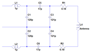
This matching network serves several purposes but primarily it matches the impedance of the antenna to the output of the reader IC at resonance. This means that the voltage across the antenna terminals is typically much higher than the voltage output by the IC allowing us to create a stronger field. Design of this matching circuit is critical to good operation.
To receive data back from the contactless card there is typically a ‘tap’ off the antenna back to the receive pin(s) (Rx) on the IC. This Rx signal is amplified and filtered in the IC before going to the demodulator.
Something else that we need to understand is that when a card communicates back to the reader it uses ‘load modulation’ which typically causes the voltage across, and current through, the antenna to change in amplitude:
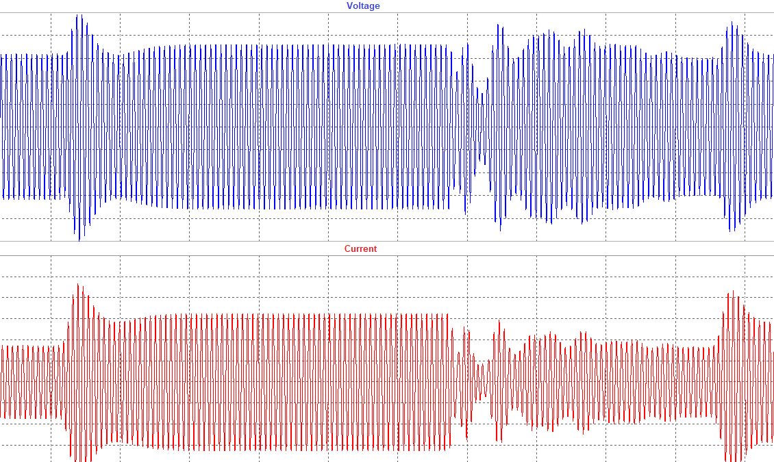
However; there are situations, particularly when the card is some distance from the reader antenna, that the effect on the voltage and/or current might be seen as a phase change only or even a combination of both amplitude and phase. This makes demodulation somewhat harder. We therefore tend to talk about modulation as a vector quantity rather than a real value.
That said; the key to card detection lies in the demodulator. Typically the demodulators are IQ demodulators which allow us to detect this vector change. IQ demodulators, in simple terms, take two samples of the received signal one in phase with the internally generated carrier (I [In phase]) and one at 90 degrees to the carrier (Q [Quadrature])
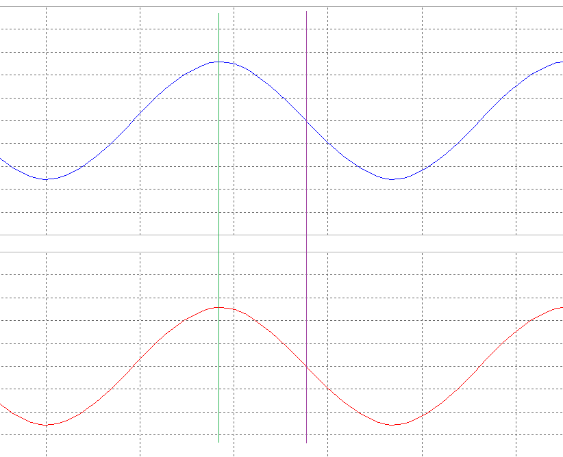
In the waveform above the blue signal is the internally generated carrier wave and the red waveform is the received signal, the green cursor line represents the I sample and the purple cursor line represents the Q sample. In this example both waveforms are in phase so if we sample the Rx signal for I we have the peak voltage of the Rx signal and at Q we have zero volts.
In the case where a card causes an amplitude change in the Rx signal we will simply be able to detect that because the I sample will change, either increase or decrease, and so taking the I output into a analogue to digital converter will give us a digital value we can process.
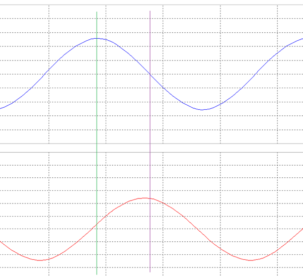
If we now turn our attention to the case where the phase of the Rx signal changes relative to the generated carrier, as shown below, then we can see that both the I and Q samples will both change and so even if the amplitude of the Rx signal remained constant we can still detect the modulation by converting both I and Q to digital values and processing them.
This arrangement of I and Q channels each being converted to digital values can be seen in the IC datasheets such as the example below:
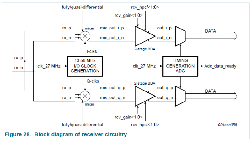
Now that we understand a little about how the demodulator works we can get back to detecting cards; If we could remember the I and Q values when no card is in the field then we should be able to know when a card is presented, simply because the values will be different to when there is no card.
This is the basis of LPCD implemented by NXP in the CLRC66303. They have provided additional registers which allow us to read the I and Q values and store them in other registers which the IC can then use to detect when a card is present.
The LPCD works by using the IC’s internal timers to periodically turn the field on for just a few hundred microseconds and sample the I and Q received and compare them with values stored in the registers, if there is a difference the IC generates an interrupt and so the MCU can wake up and attempt to read the card.
In principle this sounds great, but as with most things it isn’t quite as straight forward as it sounds!!
The most important thing is to set the right quiescent I and Q values otherwise the LPCD will either never trigger or will repeatedly false trigger. Also consider that the quiescent values will change if the environment around the reader changes, so if the reader is portable then it will need to regularly re-calibrate as the environment changes and if the reader is close to metal or other conductive objects this will change the I and Q values also.
In our implementations what we have found is that to successfully implement LPCD you need a thorough understanding of how the antenna and matching works and it needs to be well tuned. You also need to determine the best time and method to measure the quiescent I and Q values and store them in the comparison registers. Determining this takes time and will vary from project to project but once you have the right method the system works very well.
NXP suggest that you can set a ‘window’ or a range of I and Q values which allow a bit of variation in the I and Q values before an interrupt is generated, this can be very useful in some environments but we have found that once you have the correct methodology the window is usually not needed and reliable card detection can be achieved.