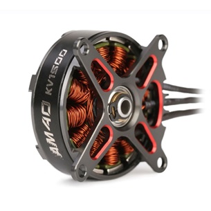
The brushless DC motor (BLDC) is becoming increasingly popular when designing products for markets such as automotive, domestic appliances, tools and industrial systems because it does away with the mechanical commutator (brushes) used in traditional motors, replacing it with an electronic device that improves the reliability and durability of the unit. Another advantage of a BLDC motor is that it can be made smaller and lighter than a brushed type with the same power output, making BLDC motors suitable for applications where space is tight. BLDC motors are particularly popular in battery powered appliances such as vacuum cleaners and power tools.
The downside is that BLDC motors do need complicated electronic management to run. For example, a MCU is typically needed to energize the stator coils at the correct moment. Precise timing is essential for accurate speed and torque control, as well as ensuring the motor runs at peak efficiency.
This blog explains the fundamentals of BLDC motor operation and describes typical control circuits for the operation of a three-phase unit.
The advantages of brushless operation
The brushes of a conventional motor supply power to the windings which, when energized, turn in a fixed magnetic field. Friction between the brushes and a rotating metal contact on the spinning rotor causes wear and power can be lost due to poor brush to metal contact and arcing.
Because a BLDC motor uses an electronic commutator instead of brushes the motor’s reliability and efficiency is improved by eliminating this source of wear and power loss. Additionally, BLDC motors have a number of advantages over brushed DC motors and induction motors, including better speed versus torque characteristics; noiseless operation; higher speed ranges and faster response. Furthermore, the ratio of torque delivered relative to the motor’s size is higher. However, it should be noted that brush-type DC motors do have a higher starting torque.
BLDC motors are available in one, two, or three-phase types, but the latter is the most common type and used here for these examples.
The rotor of a BLDC motor is constructed from permanent magnets with a number of N-S pole pairs. More magnet pairs increase torque and smooth out so-called torque ripple, evening the power delivery from the motor. The downside is a more complex control system, increased cost, and lower maximum speed.
Originally, ferrite magnets were used to make the permanent magnets but more recently rare earth magnets are being used because they generate greater flux density albeit at higher cost. These rare earth magnets allow the rotor to be made smaller for a given torque. The use of these powerful magnets is a key reason why BLDC motors deliver higher power than a brush-type DC motor of the same size.
BLDC operation
As discussed earlier the downside of BLDC motors is that they need to be driven by an electronic circuit which performs the commutation action. This electronic commutator sequentially energizes the stator coils generating a rotating electric field that pulls the rotor around with it.
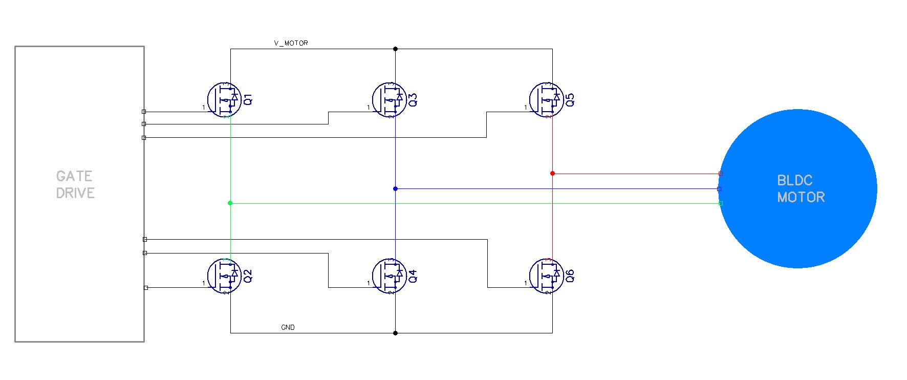
This energising is typically performed by an arrangement of MOSFET devices arranged in pairs to pass a current through each winding in one direction or the other.
When performing this electronic commutation the timing of the switching is the most critical factor, switch too early and the motor will either not run at all or have very low torque, switch too late and the motor will stutter and consume very high current.
There are two primary methods of controlling the timing. The first is to mount Hall Effect sensors on the rotor which will switch as the rotor rotates providing feedback to the MCU telling it precisely when to switch the current. The use of Hall Effect sensors simplifies the design but adds significant cost to the motor. The second method is to sense the electrical feedback in the windings. During commutation there are times when any particular winding is not energised and at that time the voltage induced in that winding by the rotor can be sensed. This method is known as Back EMF (BEMF) sensing as the voltage induced in the winding results from the back EMF induced by the movement past the magnets and collapsing magnetic fields.
However this ‘sensorless’ method has a problem; a stationary motor generates no back EMF, making it impossible for the MCU to determine the position of the motor at start-up. The solution is to start the motor in an open loop configuration until sufficient EMF is generated for the MCU to take over.
Controlling a BLDC motor
Most BLDC motors are constructed in a star configuration, in this configuration the windings are connected together at a centre point with the other end of each winding being brought out for connection to the MOSFETS
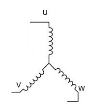
These winding connections are typically called U,V and W
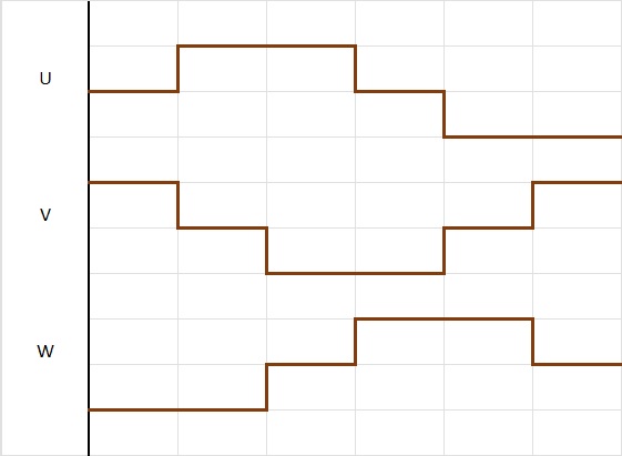
There are two primary ways of driving a BLDC motor, one method uses a six-step commutation sequence for each electrical revolution. This method energises the windings in pairs with one winding supplying current to the motor and the second acting as the return path. The third, un-energised, winding is used to sense the BEMF. This method is sometimes called ‘Trapezoidal’.
The diagram below shows the current flow, and direction, in each winding over time, at any one time current will flow into one winding, out of another winding leaving one winding with no current flow.
The second method of drive is called ‘Field Oriented Control’ (FOC). In this method all 3 windings are driven with a current waveform that approximates a sine wave with the current in each motor phase shifted by 120 degrees. There are various ways to achieve this but typically each winding is driven with a PWM waveform, the PWM duty cycle is constantly varied to create currents in the windings that are sinusoidal in shape and 120 degrees shifted from each other.
The diagram below shows the ideal phase currents. A simplified PWM signal is superimposed on one phase as an example.
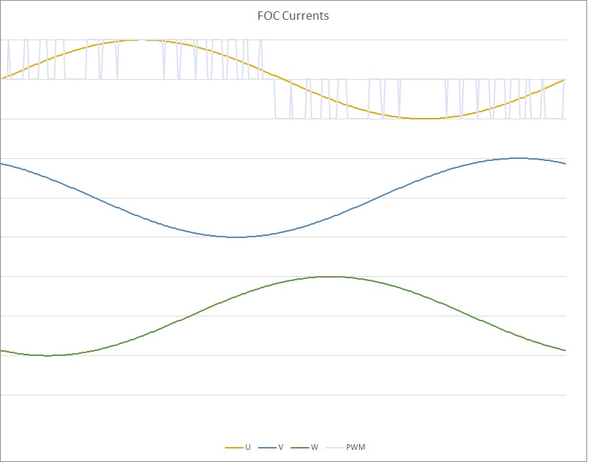
There are a number of ways of creating these sinusoidal current waveforms and the example above is only a simple example. We will explore FOC techniques in more detail in a future post.
Using FOC drive has a number of advantages. Firstly it can provide motor efficiency of up to 95%. This significantly reduces power consumption. Also; FOC can provide almost noise free operation. It also typically provides much higher and smoother torque delivery. The disadvantage is that the control electronics can be much more complex.
In Summary
BLDC motors offer a range of advantages over conventional DC motors particularly in battery powered equipment like power tools, cordless domestic appliances and electric vehicles. While the design process may be more complex the cost and space savings in production may be significant.
Touché Technology have designed a number of solutions using BLDC motors and has considerable experience in their use and are therefore able to help customers use BLDC motor technology in new products.